
 We present a series of recommendations and aspects to take into account to develop a correct electrical installation of an air conditioner.
By Jimy Danelli*
Air conditioning professionals are always receiving installation projects previously calculated to condition certain areas, however, the conditions of each space where the equipment will be installed do not have all the plumbing, electricity and even infrastructure requirements necessary for a correct installation.
The correct installation of an air conditioner consists of several parts, a good location in a suitable infrastructure space, connection of fluid drainage pipes (plumbing) and electrical protection. The latter I want to detail in this article, although it is something very simple.
This guide is aimed at complementing the knowledge of anyone who wants to experiment with electricity by assuming the risks that this represents; the one who works in the field and needs a little help to solve and carry out a task of this type.
Air conditioning systems are characterized by relatively high consumption, and depending on their characteristics (hot / cold) can be used seasonally or all year round. For this reason they must be considered as individual elements within the circuit and for their correct electrical protection a particular branch is derived for their power.
This is important because if we make the mistake of plugging the device into any socket we have nearby, we run the following risks:
a) We overload the circuit of outlets, this can translate into triggers of thermal protection when other sockets are used with other devices.
b) We are using a pre-existing circuit that was not calculated for these benefits, therefore, in the best case, only the thermal will jump.
c) By regulation and for convenience, it is necessary to be able to cut the energy individually for maintenance and other necessities. In Figure 1 we show the circuit of a characteristic house.

Figure 1.
As can be seen in the graph, there is a circuit for lights, another for sockets (where we connect low consumption devices: chargers, blenders, fans, etc.), and others for devices of higher consumption. Individually each secondary circuit has a thermal protection and wiring according to the current and power performance. As a general cut we have the differential switch (ID) that protects us from discharges dangerous to health. Limiters, fuses and other general cut elements are also used on the main board.
How do I proceed to calculate the protections, cables and costs?
I could elaborate on the theory of calculations and sizing that this work covers, but that is a subject of study of the profession and I am not interested in dealing with it here. I better want to explain the procedure with a simple and real example that I had to perform recently.
First we have to recognize the place where it is already structurally installed. It is strictly forbidden to use extension cords and adapters (irregularities that my client had). Identify the make and model of the device, measure the distance to the sectional box, and plan the shortest path of cables from the board to the socket that should be close (1m) to the air. Drawing a sketch we have something like this (figure 2):

Figure 2.
Then we have to take phase and neutral of the equipment, ground discharge from a common terminal inside the board. There will be installed a thermomagnetic switch (breker or disconnective) that will govern over the Air. Drill through the wall.
On the other hand, channel (with cable channel in compliance with the client / user) to an octagonal verification box nearby.
From there the three cables will be probed through the tube inside the wall to near the destination, passing through three octagonal boxes and a rectangular one of outlets. From the last to the outside socket should be put near the Air, cable channel (very discreet and neat because it is an aesthetically very pleasant living room, but when installing the air must take into account the aesthetics of said installation).
Therefore to start with the calculations we have to look in the user manual (if you had the prudence to save) or in the Surrey site where we find the technical specifications for each model.
The following example of table (1) tells us the physical capabilities and properties:

Table 1.
Table 2 shows the consumption:

Table 2.
Note that the highlight is the model to protect "cold alone" and "cold heat" to see the case of higher consumption. Giving the current value between 9.13A and 10.08A.
Calculation of the section of cables to be used
For that we consult in the following table (3) which of the commercial values (standard) fits the amperage requirements.

Table 3.
As a general rule it is understood that the 1.5 mm2 conductor (13A maximum that supports) would be useful to our purpose. The 2.5mm2 conductor (18A maximum that supports) is recommended. In this case the choice of conductor was limited to conductors of 1.5 for pre-existing structural reasons (the pipe with little space to channel more cables).
It must be considered that the pipe must have free space to avoid overheating. Another good reason is to lower the cost of materials (2.5 more copper, more expensive). It is made clear that whenever possible, using 2.5 is safer.
Calculation of meters of cables to be used
As seen in the sketch, we are about 13m long and to that we must add between climbs, descents and turns, 6m more. How is it better as long as it is over and not missing, that they are 25m of 1.50mm2 cable. Since we must carry three cables, which are of the standardized colors:
25m brown (phase)
25m celestial (neutral)
10m green/yellow
In total 60m of cable.
Thermomagnetic Switch Calculation
Of the commercial values that we have 10AMP or 20 AMP, I stayed with the 16, so that it does not work very to the limit, but, as we will see later, with one of 10 it would go well and the cables would be well protected as well. It can be unipolar or bipolar (Figure 3).

Figure 3.
Calculation of outlet
What should be done is to look at the plug of the artifact (20A), from there look for a 20A socket.

Figure 4.
Calculation of materials

Table 4.
These prices (in dollars) are approximate and estimated. Rather, they are indicative, every time a budget is put together, the updated prices should be consulted.
Calculation of construction time
This depends a lot on the skill of each one and is necessary especially if it is for a client. It is important to determine the intervals in which a scheduled cut must be made and that there are no downtime due to not being able to cut (for example servers in business). In addition, setting a cap to achieve a goal and gives the client an overview of the work.
Broadly speaking, you must work on the 30' sectional board (uncover, place, connect, drill, channel cables, etc.)
30' more on the other side placing cable channel.
30' passing tape and cable in each section between box and inspection box (x3)
30' more placing cable channel and socket at the end.
In total it gives 2 hours 30' but it is not bad to round in 4 h (half a day of laburo) since unforeseen events may arise (unforeseen events will arise).
Labor cost calculation
This is very particular and there is no set rule. That is, each professional sets their fees depending on experience or personal pretensions.
a) By time: if one intends to earn US$20 per hour, then, apart from the US$85 in materials, the client is given US$80. In this way an unbeatable budget is spent economically speaking, but the stipulated times must be met by doing quality work, otherwise we lose out.
b) By mouths: Some prefer in advance to put a price to each section where you work (mouths) and so if a mouth is a passage box has a price and is a shot and period, another. This is prefixed and detailed for example: in the 50p board, in a 30p pitch box, the 40p Air outlet, the 20p pipes. Leaving about 50 + 30*5boxes + 40 + 20*2channels = 280p
c) By meters of circulation: we can put a price to each meter of work differentiating those that are passed from cable in pre-existing pipe (10p / m) and external channeling (5p / m). Remaining about 130preex + 30channel = 160p
This is for guidance. The details of my billing in this case I reserve, but we must say that after trying the different methods of budgeting, the "b" is the most ideal since it is more realistic.
It is a simple but important job for the proper functioning of the circuit. The current measurement gave 6.7A (which made me think of the thermal of 10A) and the optimal result is when the work is finished, it is not noticeable that there are added cables (the cable channel or gutter behind the board must be the most hidden). Obviously in the sectional board you have to label the new control for user management.
These recommendations allow the professional to have an estimate of the tasks and activities that must be carried out only in the electrical installation to install a Split or compact equipment.
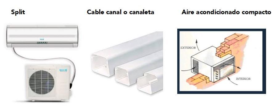
Figure 5.
* Jimy Danelli is an air conditioning and refrigeration maintenance consultant. You can write to the email: [email protected]


¿Calcular el breake y el cable conductor para un split tipo ducto de 24.000 btu/h con un voltaje de 240 y una potencia de 3.000 vatios?
acondicionado .220v. Onpuede operar con ewe voltaje q llegua
Hola, Jorge. El Ing. Jimy nos compartió la siguiente respuesta a tu pregunta: "Los sistemas normalmente viene diseñados para trabajar un 10% más o menosl es decir que hasta un aproximado de 242v no deberían presentarse problemas, pero al estar por encima de 242 pasando de los 250v puede generar daños, no tanto al motor condensador, evaporador y mucho menos al compresor, pero sí en algunos componentes como la tarjeta de control, que son componentes electrónicos más delicados y que pueden sufrir recalentamientos como en el puente rectificador, en los transformadores, entre otros elementos electrónicos más propensos a sufrir por los sobre voltajes o por las caídas de tensión que estén por debajo de un 10%".
Hola, Albert, el Ing. Danelli nos envió la siguiente respuesta a tu consulta: "Perfecto, los protectores térmicos, como su nombre lo indican, protegen únicamente por variación de amperaje y temperatura, si el voltaje falla no lo lee directamente. Esto puede que afecte el equipo si por ejemplo el voltaje está muy por encima, o por el contrario muy bajo, claro que cuando el voltaje baja el amperaje sube y puede que dispare el térmico, pero esto depende del ajuste del protector térmico".
Hola, Paola, el Ing. Jimy compartió la siguiente respuesta a tu consulta: "Es recomendable utilizar un cable N12 para que en posibles arranques que supera 3 veces la corriente nominal no esté en el límite del aislante de ese conductor"..
Pd. más allá de que correspondería uno para cada uno por tema mantenimiento.
Hola Carlos, el Ing. Danelli nos compartió la siguiente respuesta a tu consulta: "Hola saludos amigo Carlos, efectivamente es necesario colocar uno para cada equipo, ya que pudiera generarte una falla y se desconectarían los dos a la vez, otra cosa es que al conectar pueden arrancar simultáneamente superando el RLA para ese automático".
Hola Melvin, lo primero que debes hacer es buscar con tus respresentantes de marca, quienes deben generar espacios para capacitarte. Si eres indipendiente, te recomendamos que te acerques a las asociaciones relacionadas en tu país. Las asociaciones también realizan capacitaciones constantemente.
Saludos.